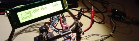
I have made some modifications of ADF4351 OE6OCG Arduino sketch: Using rotative encoder instead push button’s. Add a STEP button with 10M/1M/100K/10k/6.25k step’s size. (you…
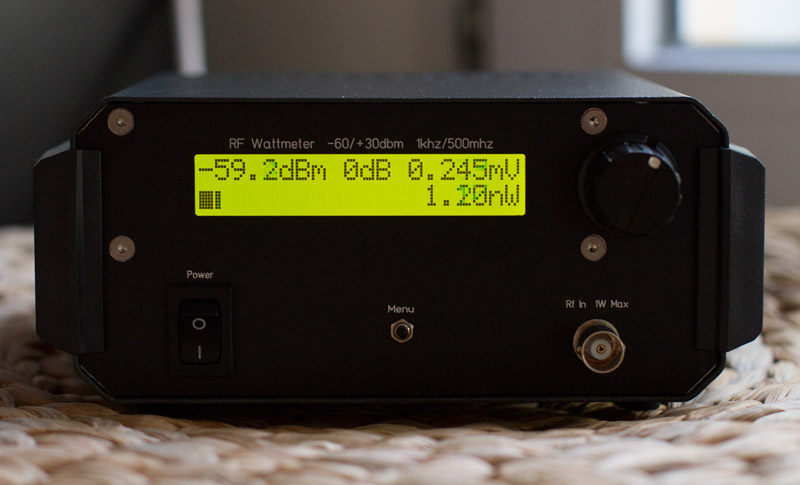
I have just finished my OZ2CPu wattmeter, The uncalibrated signal response is: +1/-1 dB from 1MHz to 450MHz. Input SWR will varry from 1.00 to…
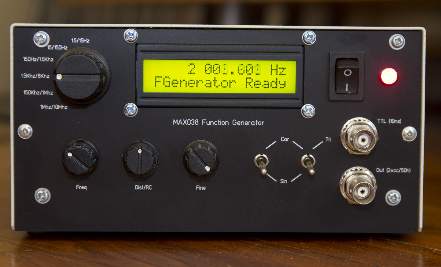
This project is too old, only for reference because Max038 is discontinued, and i have sadly lost the layout file, right now, its better to…