Small prototype of combination between trackuino and DRA818V,
Overview
« Trackuino is intended for use by licensed radio amateurs. By operating on the standard APRS frequency, the signal can be picked up by an Internet gateway and reported on aprs.fi, so anyone with an Internet connection can track the tracker »
The idea of this project was to build a trackuino board with small gps module, low power arduino pro mini (3.3v @8mhz), a VHF transceiver DRA818V, and power management integrated. 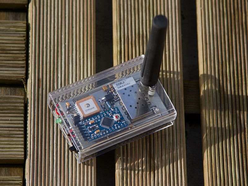
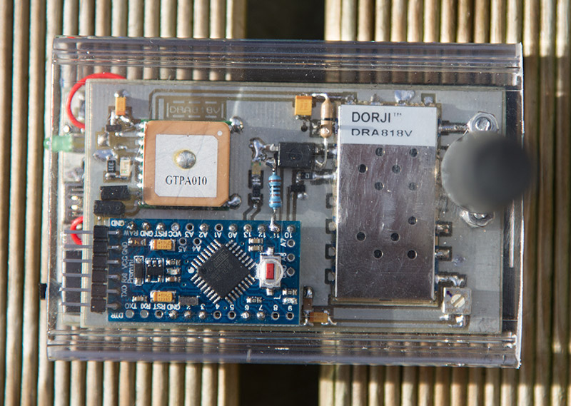
µC: The Arduino pro mini is intentionally clocked to 8mhz to ensure a less power consumption. Trackuino code was modified to send data to the VHF module, a resistors divider provide voltage batterie monitoring, and a LM60, the global board temperature. PTT on pin 10, Wakup/Sleep mode control on pin 11, and APRS audio modulation, pin 9, with a capacitor link and adjustable resistor (100k).
GPS: is a 4D Systems | GPS-PA6B (16x16mm!), Enable pin is wired to a MOSFET, for a futur power management control function (pin 2 of Arduino).
Radio: Ensured by a Chinese TRX DRA818V VHF module, power output is selectable between 500mw/1W, the module is drives by a UART communication bus on pin 7/12 from Arduino. also, he provide a Power saving control mode. I have put a low pass filter from minicircuit to avoid spurious modulation, the antenna is a 169Mhz version from Lextronic on a SMA connector. All of component are powered under 3.7v.
Dimension are 80x56mm. Weight 78g.
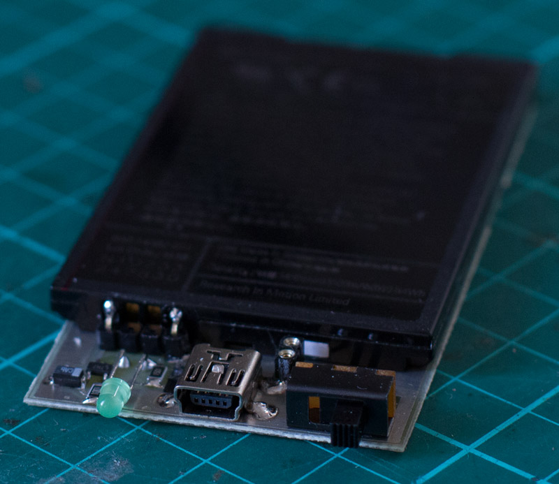
Power: A batteries from smartphone provide 3.7v@1450Mah, and can be charged with a dedicated chip, LTC4054.
Trackuino modified source code can be download here.
Schematic is here. Fell free to improve it.
If you are a licensed radio amateur you can use this @30db power on VHF APRS band 144.800, 144.390. If you are not, the ISM European 169mhz is open @27db max power output with 1% duty-cycle without licence. Be carreful to respect your local laws.
excellent do you have any fritzing schetc?
Also if you are transimiting something in this specific frequensy , everybody in this freq can listen your data?
what if someone got two of these moduiles
TX and RX and TX send Long,Lat. and only the specific RX wants to get those data ? can this be done , or you have to make some kind of encryption between those Server and Client machines?
excellent do you have any fritzing schetc?
– NO, no needed in fact.
Also if you are transmitting something in this specific frequency , everybody in this freq can listen your data?
– YES, since is APRS
what if someone got two of these modules TX and RX and TX send Long,Lat. and only the specific RX wants to get those data ? can this be done , or you have to make some kind of encryption between those Server and Client machines?
– You can implement an encryption, as you want of course, but it’s not required, since is TRX modules, you can send long,lat with one module and receive with another in same frequency, sensitivity is -122db
The amateur license in the US which is required to transmit in the 2 meter band (144 MHz) forbids encryption. The FCC has been so far unwilling to bend on that though a number of amateurs have made requests to add encryption to the rules for VHF/UHF.
hi
where do you define the gps object? I got an error in line 122 ( gps.encode(Serial.read()); ) —>gps was not declared in this scope
regards
/alex
Hello. What is the version of arduino IDE you use ? Code need to be compiled with v1 if i remember. I will check when i back to home next week.
Hi
I’m interested in using your project for HAB research. I was wondering if you have a more comprehensive parts list. More specifically, where did you purchase your optocoupler and what diodes are you using?
Regards
Margaret
hi,
I actually use 1.6.8 on Mac, I have tried also 1.0.5 on Mac with another error (undefined reference to setup/loop)
which version of 1.x have you used?
regards
/alex
I have renamed the scatch and the folder to trackuino (without the version number in it) an get the old error (gps was not declared in this scope…) with ice 1.0.5
code fixed, thx
Hi
I’m interested in using your project for HAB research. I was wondering if you have a more comprehensive parts list. More specifically, where did you purchase your optocoupler and what diodes are you using?
Regards
Margaret
hello, i use an generic optocoupler because i have experienced problems with the dra818v module (the magic of Chinese’s products), some people use resistor divider like =>, https://hamprojects.files.wordpress.com/2015/07/dra818.png , for PD pin, to drive PTT pin i use 2N7002 transistor. also in any case check the level needed into the datasheet.
What do you mean generic optocoupler? If I were to buy one from mouser, what type of requirements do I need? Sorry to be so lame, but I’m new at this.
i use a PC817 , http://www.futurlec.com/LED/PC817.shtml
Why not use LORA network ? Currently many stations placed in EU.
You can of course, but this application is intended to amateur use (no external cost)
you have wrong audio pin 9–> on schematic the right one is arduino pin 3
73 de Andrej
right, you can use 3 or 11
I’m planning to use this project as a starting point to something bigger. Similar to what has been posted on the ARRL website, I’m going to try and sort out how to use the APRS system to remote control a small robotic platform by sending commands to it as « One-liner » messages. Obviously, I haven’t yet worked out what needs to be changed in the code for this tracker to recognize those one line messages and interpret them as commands. Do you have any ideas there? If you are still actively working on this project, perhaps we can exchange email on the subject?
Thank you for putting this online.
KG7WPQ
Hello Weird Lab,
Thanks for this informative post. I am currently also trying to learn about the DRA818V module, and using it in combination with a 3.3V Atmega microcontroller.
There are a few points that I currently don’t understand – which isn’t that surprising, given that I am pretty much a novice in this field. Perhaps you, or someone else who comes across this comment could try to explain. This would be greatly apprechiated!
* the PTT transistor: is the external transistor just there as a « convenience », to invert the signal from the microcontroller and make it default to receive? Or is there any other value to it? (e.g. driving the PTT pin with more current?)
* the PD optocoupler: you mention above that this works, but other people also use resistor dividers … I am curious as to why? What happens when one connects it simply to an output of the microcontroller and drive it high or low? (Is the radio module sinking current through the microcontroller when PD is low?)
* the passives between the audio pin and the microphone input: at the end the voltage should be about 100 mV peak-to-peak for the radio, am I right? What values (or ratios) did you end up using for your 100kOhm trimpot at the end?
I have also seem designs where the coupling capacitor is at the other end, right at the microphone in. Does this make a difference?
Thanks a lot, with kind regards
gohai
Hello,
Sadly, the datasheet do not provide a lot of information’s …
– to switch to « Transmitting » mode, Tx, you just need to put PTT pin to ground, by default if you leave this pin floated, the DRA818 will be in RX mode.
– yes other people also use resistor dividers, but in my case it was unstable
– for your last question is depending of kind of modulation or bandwidth desired, i have used a 100k to adjust as better the quality of modulation.
keep in mind it’s a very cheap TRX, and after testing a lot of , its not the same quality for all product, (as always with Chinese and cheap product).
so, the way is to made a prototyp
Hi,
Is it possible connect audio output from pin 3 DRA818V to my small Raspberry PI with USB sound card to decode APRS frames when TX not transmit using your solution ???
not sure it’s will work well , because the signal come from a DSP (and distorted) not from discriminator output
Thank you for replay.
I don’t have LM60 sensor but I have very popular sensor DS18B20. Can I use this sensor instead LM60 without modify code ??
73 Waldek
Hello Waldek,
Sadly no. Lm60 is a analog sensor. Ds18b20 use 1-wire connection (digital output).
Hi,
Thanks for important for me information.
Ok I have found information about analog sensors:
http://www.instructables.com/id/Temperature-Sensor-Tutorial/
and I suppose that TM36 or LM35 sensors will be OK ??? I am asking about replacement sensor because at current it is difficult buy in my country LM60 for this reason I have looking others sensor to use
73 Waldek
Ups sorry I have wrote wrong name sensors in my previous post not TM36 but TMP36
http://www.ladyada.net/media/sensors/TMP35_36_37.pdf
I hope it will now ok replacement LM60
73 Waldek
yes it will work, but you need to change the scale factor in the code, (if i remember, around sensor_avr.cpp)
Linear Scale Factor is 6.25 mV/°C for LM60, AND 10 mV/°C for TMP36
(LM60 can be get from Ti for SAMPLE, then you can test before buying some on ebay … or not)
Hi,
Many thanks for suggestion and advise to request free sample for TI LM60. I have register on TI but it is look I can request free sample because IT send free sample only for a corporate (.com) email 🙁 but I don’t have corporate email which have on end .com
I have found in sensor_avr.cpp formula where is used scalar for LM60
case 1: // C
// Vo(mV) = (6.25*T) + 424 -> T = (Vo – 424) * 100 / 625
return (4L * (mV – 424) / 25) + CALIBRATION_VAL;
for TMP36 should be ???:
case 1: // C
// Vo(mV) = (10*T) + 424 -> T = (Vo – 424)/ 10
return ((mV – 424) / 10) + CALIBRATION_VAL;
I am not sure that we need return temperature in Integer Constants and we need use for example:
case 1: // C
// Vo(mV) = (10*T) + 424 -> T = (Vo – 424)*10/ 100
return (10L*(mV – 424) / 100) + CALIBRATION_VAL;
73 Waldek
Hi Weird Lab
I have collected all parts and start with build your construction. I will be use TMP36 instead LM60 and I will be use opto-coupler 4N25. But I have review your schematic and photo I have see that you are use 2 resistors with PC817. What kind/ value resistors your are use ?
73 Waldek
Hello, Waldek
On the top is a 0 ohm wired Vcc to optocoupler, on the bottom is a pulldown resistor (1 or 10k)
Ok thanks,
Pleas look like on schematic:
http://www.hownottoengineer.com/projects/cnc/images/4n25.png
Resistor R1 is 0 ohm or you wrote that 0 ohm is between Vcc and 5 PIN 4N25 ??
R2 is pulldown (1 to 10 kom) ???
sorry, i do a check on the board,
if you take your schematic, in my case, R1 is 1K btw pin 11 and optocoupler (diode), and Vcc to optocoupler is 0 ohm (transistor).
some use simple resistor divider, https://hamprojects.files.wordpress.com/2015/07/dra.png?w=660
Hi Weird Lab,
Please look on my small modification of your schematic
http://sp2pmk.tvk.torun.pl/data/uploads/aprstracker.png
I have made to my electronic parts , I have different module GPS and sensor and optocoupler.
It is all OK ???
you can use what you want of GPS module, just ensure you use the good baud-rate.
you can connect the opto directly to Vcc, in my case i use 0 ohm resistor to Vcc because it was a strap.
Hey so i want to know which diode are you using ?
hello, which diode ? there is only 2 LED’s and the diode of the optocoupler
diode of the octocoupler
Hi,
I’m upload the code my Arduino Nano.
But, doesn’t work. trackuino1.51_rev2.ino
Before I upload checked the code with Arduino IDE, don’t give error or warning message.
And of course I setting up the conf.h
When uploaded not error massege.
It does not do anything.
I connected one LED to PTT and one to GPS power port.
The LED lighting on inmediately When finished program upload or press reset button on the Arduino.
The RX LED flicking on Arduino when GPS modul send GGA messages.
The GPS is fixed.
Thank you any idea.
Tony
its fixed
The link http://www.f4huy.fr/wp-content/uploads/2016/01/DRA818V_Trackuino.PNG is broken.
Do you have the schematic in another address?
73’s
hello, old domain is not longer available, it’s fixed, thx
How do you set the transmit frequency?
Thank you,
cheers
frequency can be set into the arduino sketch
Thank you, I missed it in the main code. I thought it might be in the radio lib. or the config.
A very nice project, I have it working hard wired to my Igate now to make the radio module transmit.
I would like the transmitter only transmit 20 or so mw, Guess I need to go inside the module and see what’s there.
Thanks again.
Cheers,
Doug k6sts
I made a couple of these but could never make them work right.
The unit transmits APRS to my radio but the range is LOUSY (a couple of feet!!). I suspect there is a problem with the DRA818V module. I got mine from ebay from some China vendor. Perhaps they were selling modules that were not working right.
Another one of the units I can barely hear the APRS on the radio.
– what is the voltage level of your unit ? with low voltage, don’t expect 30dbm out, so a very long range
– you need a perfect antenna match, and fine tuned for 145mhz
– low pass filter do -1db att
– signal is weak, you need a receiver system with a good antenna on a high point
Many other thing can affect transmit and receiv, in mobile i prefer to use my 8w unit, it’s work in all situation http://www.f4huy.fr/?p=1122
Hello, i have a short question. Why needs the DRA818 TXD Pin 3,3Volt and not the RXD Pin? In my understanding TXD is transmitting Data from the DRA818 and RXD is receiving Data to the DRA818. When i use 5V Atmega, i think there should be a voltage devider for 3,3Volt to the RXD DRAs RXD Pin where the TTL levels on the DRA818 are 3,3Volt.
//////////////////////////
#define PwDw 11 // Power Down pin. This need to start low, then be set high before programming.
#define DRA_RXD 7 // The Arduino IO line that is connected to the DRA818’s TXD pin. 3.3V only
#define DRA_TXD 12 // The Arduino IO line connected to the DRA818’s RXD pin.
SoftwareSerial dra_serial(DRA_RXD, DRA_TXD); //for DRA818
//////////////////////////
Thanks, Andreas
In this project we dont use Rx pin.
If you use atmega at 5v you Need level translator
Hello can we listen Ais data with this module 161.975 MHz
Output format nmea0183
But ı think when we receive audio it must be pass from gmsk.do you have experience with that ?
Hi, DRA818V can run from 134 to 174MHz, so, I can say yes. I think you can try to listen with squelch opened,
may need a LNA and band pass filter in front