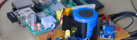
As you know, if you use Raspberry, the operating system on SdCard is very fragile, that the reason you need to power off properly the…
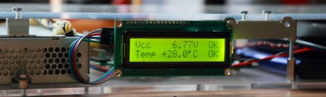
A small gadget to monitor the power supply and enclosure temperature of your Raspberry. My Raspberry Pi server host a OpenVPN service, Onion Pi Tor…
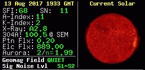
Based on information’s from N0NBH Solar Banners, (hamqsl.com), i have decided to build a small banner for Windows desktop (work under 7 and 10, not…
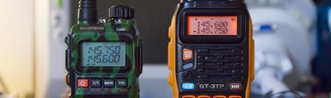
I have get my Baofeng GT-3TP to replace my UV-3R+ from ebay (seller uncleb2c), you can find it around 45€ (shipping included) with usb programming…

Patrick F1EBK, m’a prêté une antenne NanoBeam M5, mon QTH étant a 730 mètres a vol d’oiseau, et en vue direct du relais F5ZEQ, qui…