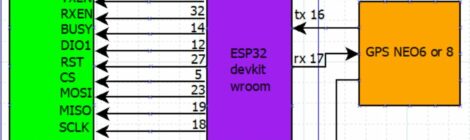
Une description d’un tracker APRS, basé sur le firmware « DIY 1W » de richonguzman , firmware dispo depuis https://github.com/richonguzman/LoRa_APRS_Tracker La cœur est un ESP32 DEVKIT Wroom, relié…
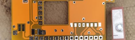
Un modèle non basé sur module TTGO, juste un ESP32, un module radio HPD14A (le même que sur les TTGO), sans ecran LCD, un GPS…
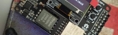
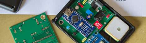
Ayant vue passer des trucs intéressant sur Tweeter à propos de L0Ra et d’une utilisation amateur, j’ai donc commandé via Aliexpress une carte TTGo LoRa32…
Currently testing and prototyping, based on DRA818V with Atmega328P and GPS EM406, RF out up to 8W with a RA08H1317M from Mitsubishi. It’s around the…
This little cheap Chinese transceiver can be found on Ebay, or Aliexpress for 60$, supporting VHF/UHF, can Tx up to 25W. A complete description…